4" solid state coil
My second coil was a solid-state coil, which drives the primary continuously with MOSFETs instead of pulsing it with a capacitor and spark gap. This allows operation directly from rectified 120V mains, an improvement from having to drag around 50 pounds of high-voltage transformers. However, MOSFETs are less robust switches than spark gaps and are notorious for failing often in this application, sometimes violently. I blew some MOSFETs while running the coil from smoothed DC and right now it is inoperative.
The streamers from an SSTC take on a fibrous quality and produce a low hum (or hiss if run from smoothed DC) instead of the harsh buzz of a spark gap coil. The peak current is low and arcs can safely be drawn to a metal rod held in the hand. This produces a mild tingling sensation as the current is conducted through the body's capacitance. Care must still be taken, though, as direct contact with the streamers will cause a deep RF burn that takes a long time to heal.
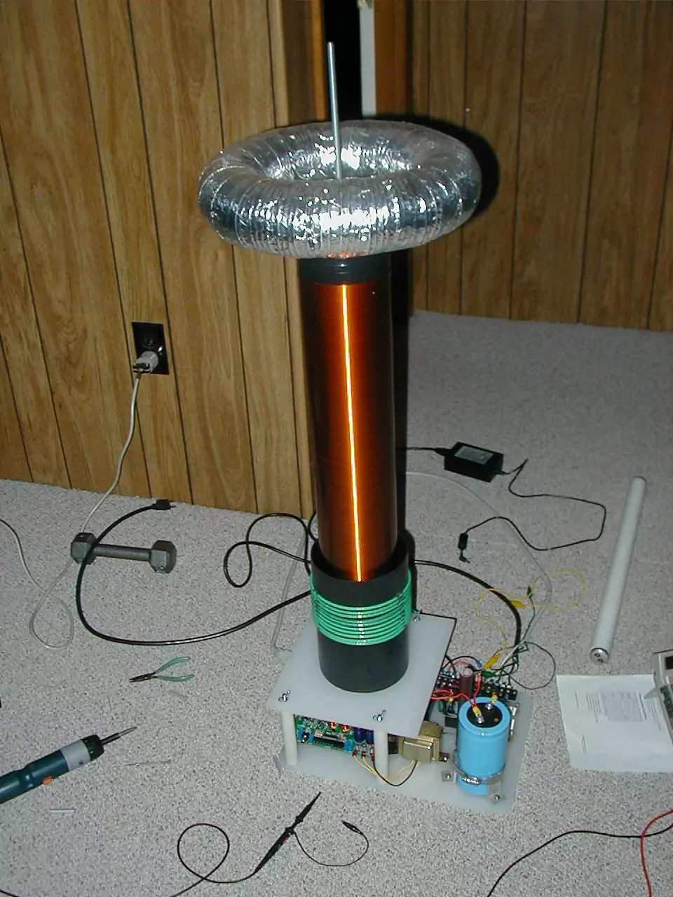 |
This is the whole unit. I think it looks nicer than most of my projects. The secondary is about 1600 turns of 28AWG magnet wire on a 4.5" PVC form, coated with enough coats of polyurethane to make it feel smooth. The primary is 10AWG stranded wire, wound on a piece of thin-wall plastic tube that sits in a groove milled in the base. |
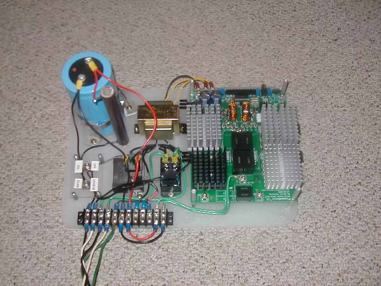 |
This is what is underneath the deck. You can see the section that produces smoothed DC for audio modulation (to the left; only partially successful), the main relay, the power and cap discharge switches, and the electronics. |
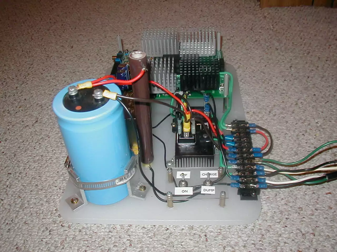 |
Here is the power section. The switch on the right discharges the capacitor through the big wirewound resistor next to it. Behind the switch plate is the bridge rectifier that feeds the cap and a single rectifier for half-wave, and behind that the relay that controls power to the power circuitry. The two jumpers on the far right control whether the MOSFETs are fed with half-wave or smoothed DC. |
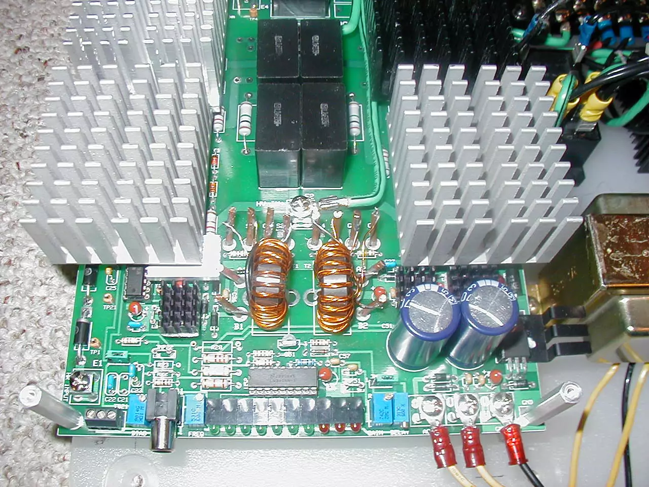 |
This is the circuit board. I did not design the board; it is a 'PlasmaSonic II' purchased from someone whom I no longer want anything to have to do with. I populated it and made some modifications to get around various limitations, such as the colossal suck demonstrated by the original MOSFET gate drivers. |
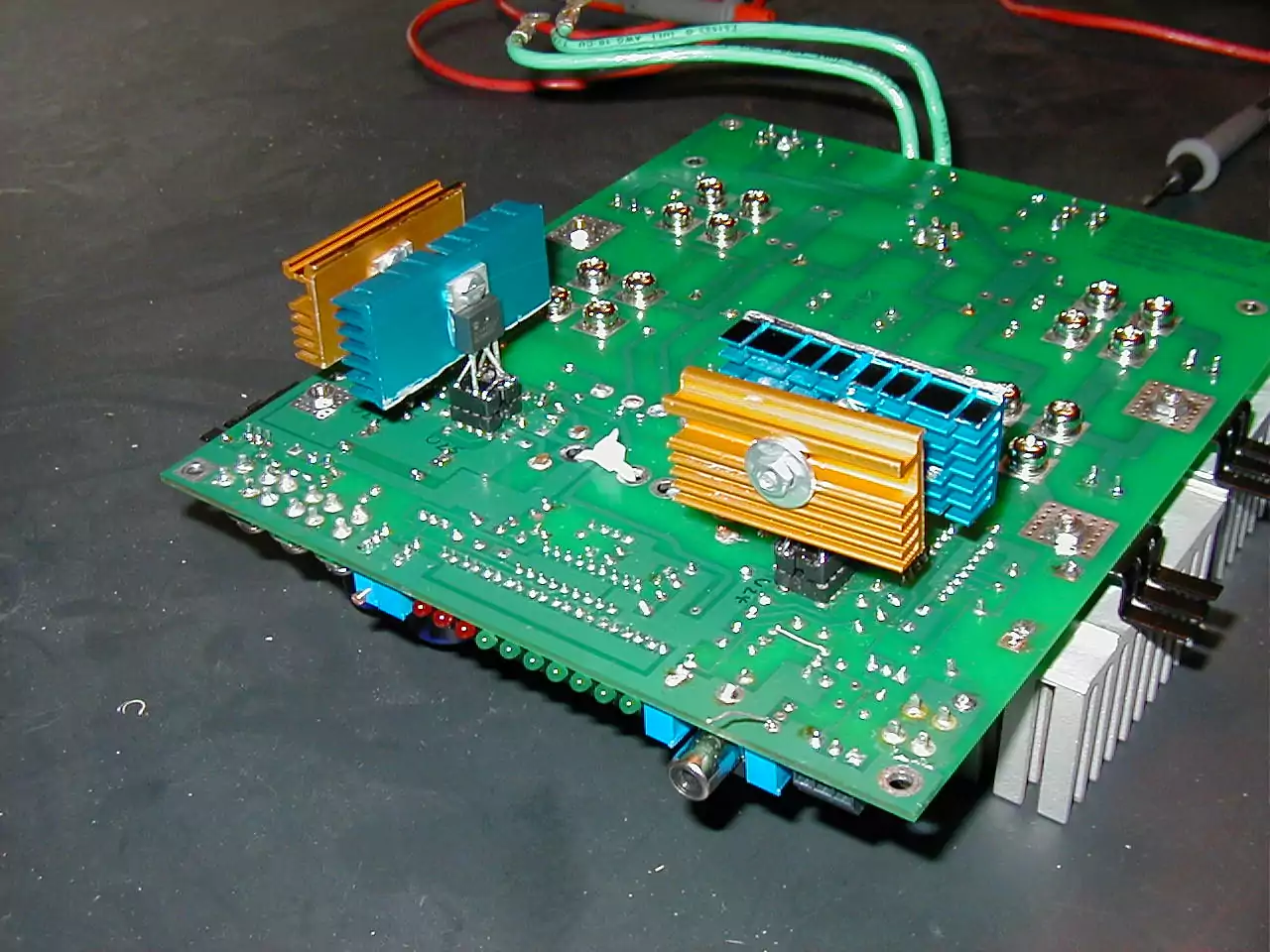 |
The gate drivers were TC4421 and TC4422 chips from Fairchild Semiconductor. They can supposedly pump 9A peak to switch MOSFETs with high gate capacitance, but they get extremely hot and burn out driving the IXFN44N50 FETs on the board. You will note above that there are small heatsinks atop the gate drivers. The solution I came up with was to use the same chips, but in a TO-220 case much more capable of dissipating heat than the usual DIPs. Since the heatsink would not fit on top, I moved the sockets to the bottom, fitted each driver to a DIP socket, and plugged them in. Later on I heard about Texas Instruments' UCC3732{1,2} chips that have mostly the same specifications but somehow manage to produce sharper edges with lower power dissipation. |
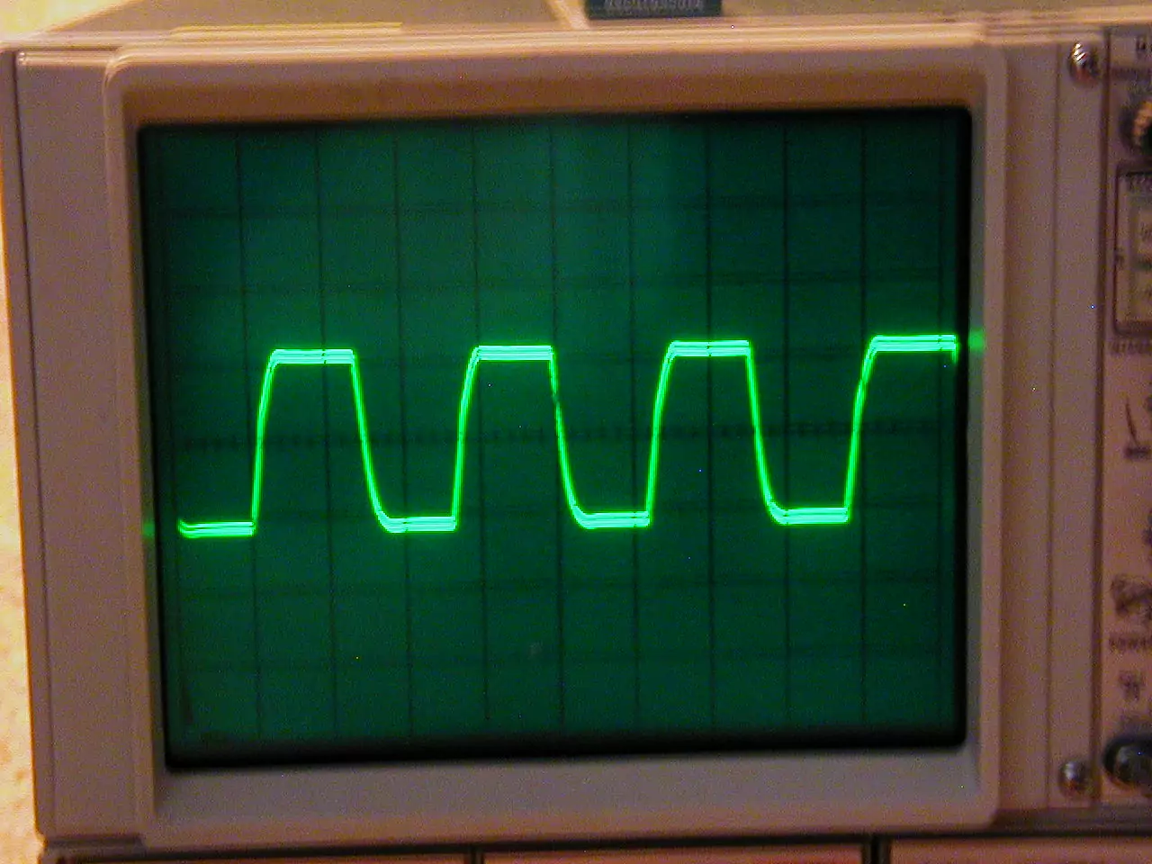 |
Here is the gate waveform. The horizontal scale is 2us/div and the vertical scale is 10V/div. You will note that the switching is still rather slow, which probably contributed to the death of MOSFETs. |