chaotic driver for wave array
introduction
I wanted to make some sort of driver for the LED wave array, to give it some activity when nobody is playing with it. The edge connectors are meant to connect to other boards, but can also be used as an interface to drive arbitrary signals into the array.
I originally considered using a DAC and microcontroller to drive arbitrary programmable signals, but I stumbled upon chaotic circuits and was intrigued by the idea of having a fully analog driver for the fully analog wave array.
chaos from order
Chaos is not randomness. Chaotic systems can be constructed using only deterministic differential equations. However, such systems exhibit unpredictable, exponentially divergent behavior, while always remaining within some bound. The boundedness with complex behavior and sensitive dependence on initial conditions are what define a chaotic system.
An example of a simple chaotic system is the double pendulum, a pendulum with another pendulum hung from its end. For certain configurations and starting conditions the behavior is periodic, but in many cases the bottom pendulum will swing around wildly and unpredictably. Tiny changes in the starting state will lead to entirely different behavior after just a few swings.
One might think that real chaotic systems are unpredictable because uncertainties in measurement make it impossible to exactly determine a starting state, but this is only part of the problem. Even in theory, the systems of differential equations that describe chaotic systems cannot be solved analytically.
prototype
Chaotic circuits are pretty simple, usually just requiring a few opamps and passives. Fortunately I had many opamps left over from the various LED wave array prototypes, so I started by dead-bugging an opamp and attaching passives to it:
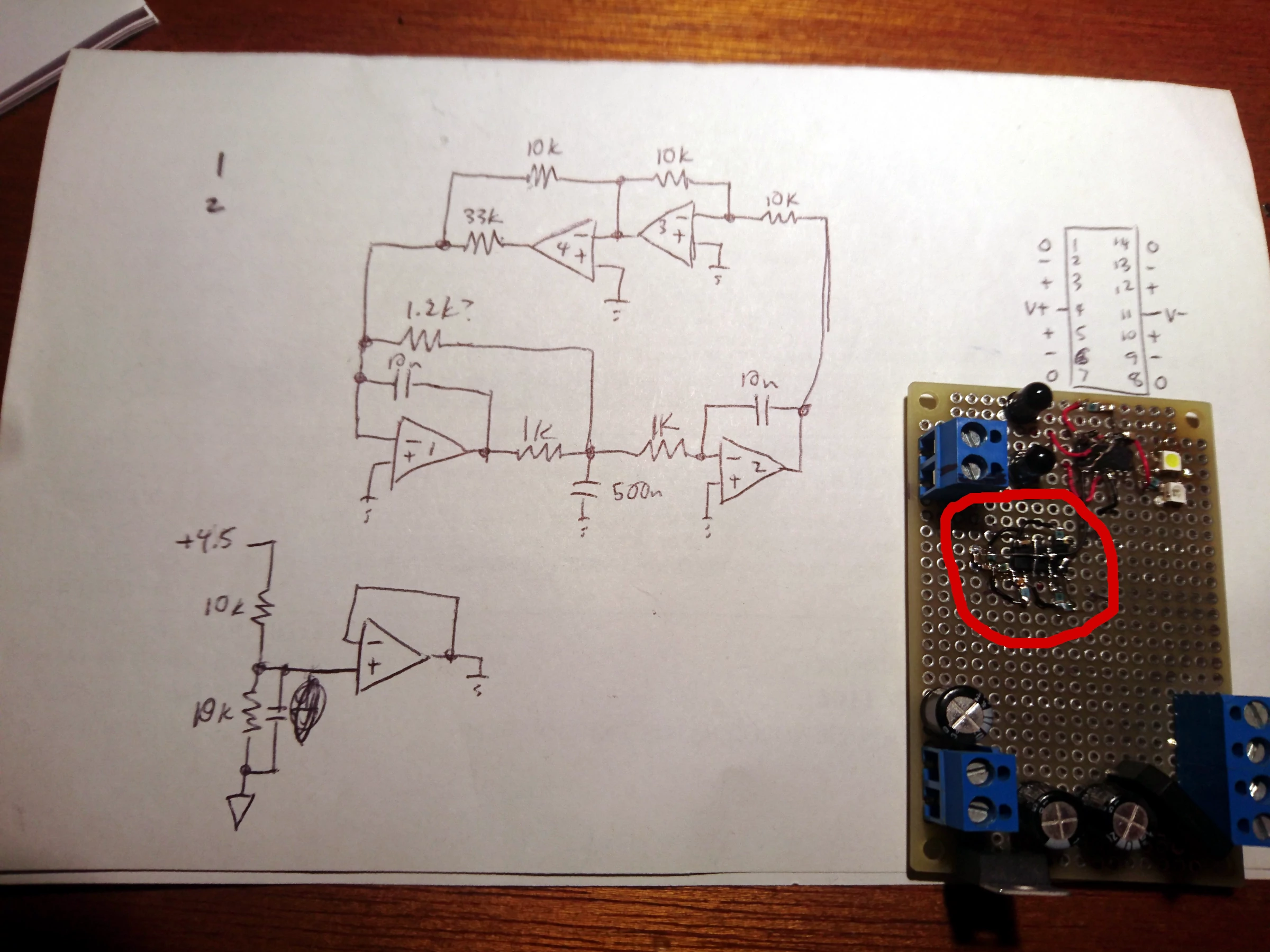
This circuit was based on one found on the Falstad circuit simulator "Chaos 1" under Circuits > Op-Amps > Chaotic Circuits. In the schematic, the ground symbol is actually a half-supply-voltage reference created by the buffer shown at the lower left. The actual chaotic circuit is only the circled cluster of components; the other stuff is unrelated. It oscillates at around 2kHz, though its exact behavior is unpredictable by design.
However, actually getting chaos out of it is hard. From simulations I knew that the circuit was very sensitive to the value of the resistor marked "1.2k?", and the circuit required tuning to get the desired behavior. It was originally 1k, which happened to put the circuit in an island of stability with period 2. I played with the value by changing and stacking resistors until I found that 1.1k (three 3.3k in parallel) yielded chaos.
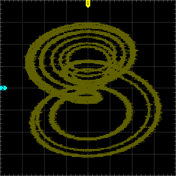
With my scope in xy mode, I probed the output of opamp 2 (x, 50mV/div) and the 500n cap (y, 500mV/div) and saw a classic double scroll:
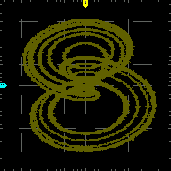

Continuous chaotic systems need at least three variables and a nonlinear element. The three "variables" in this circuit are the three energy-storing elements, namely, the capacitors. The source of nonlinearity may not be very obvious, but note that opamp 4 is connected as a comparator, whose output is summed with the output of the inverting amplifier (opamp 3). This provides a N-shaped transfer function with a discontinuity at 0V.
I built this partly because I didn't recognize the nonlinear element and couldn't believe that it would actually work, so I followed the time-honored tradition of "fuck around and find out". Well, I definitely found out.
implementation
After confirming that the circuit works and getting some pretty pictures out of it, it's time to adapt it to drive the LED boards. The most significant change that must be made is to bring the "frequency" down from 2kHz to around 1Hz. This cannot be done by simply adjusting component values - because the RC stage is unbuffered, we do not have the freedom to tweak other resistors connected to that node. I added a buffer to this and changed a handful of other things, using the Falstad simulator to verify the behavior.
This was the final design:
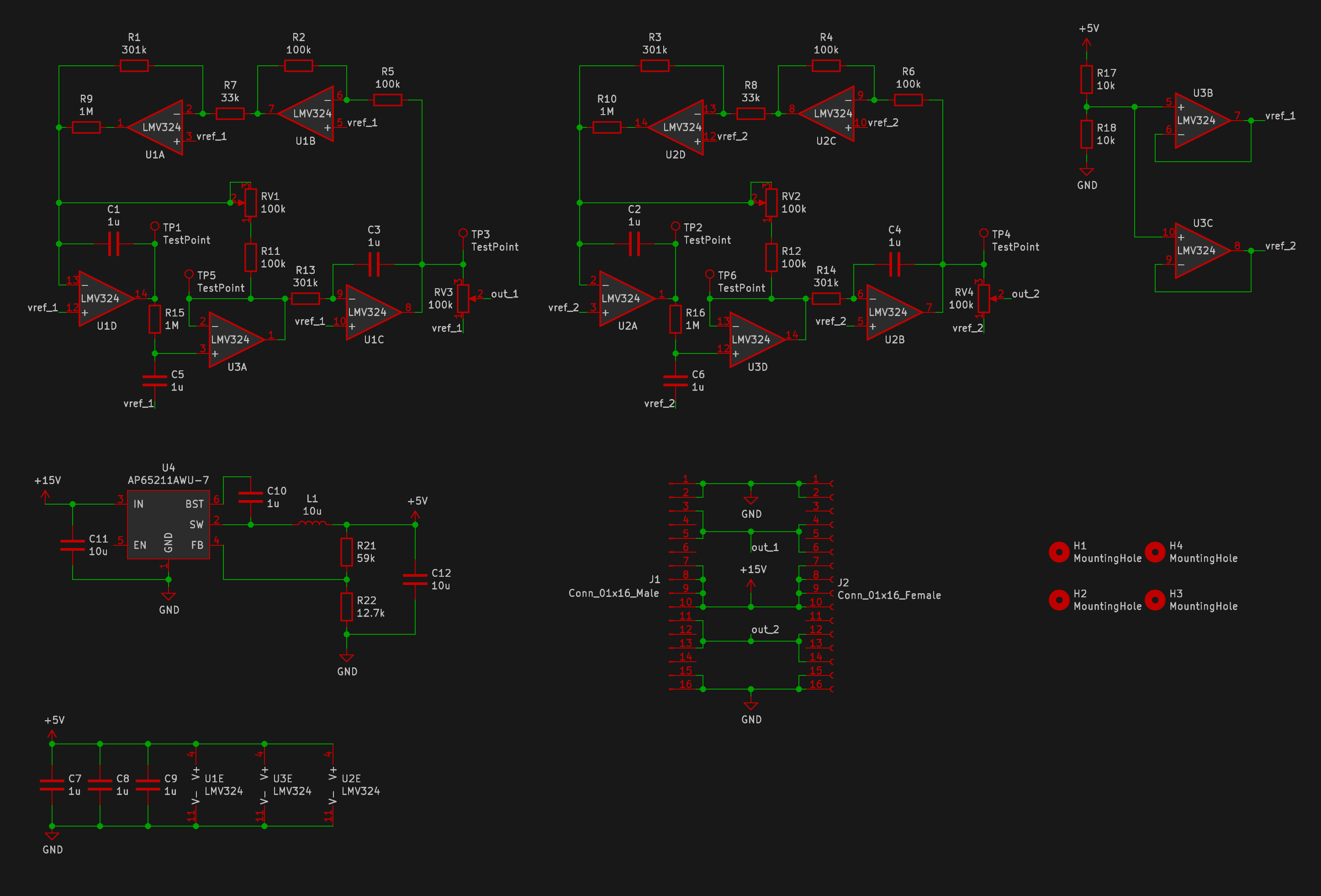 schematic
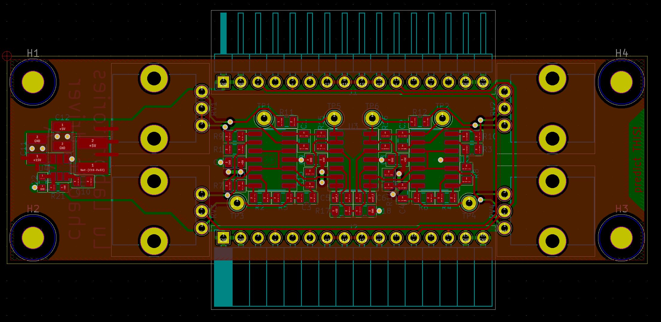 layout
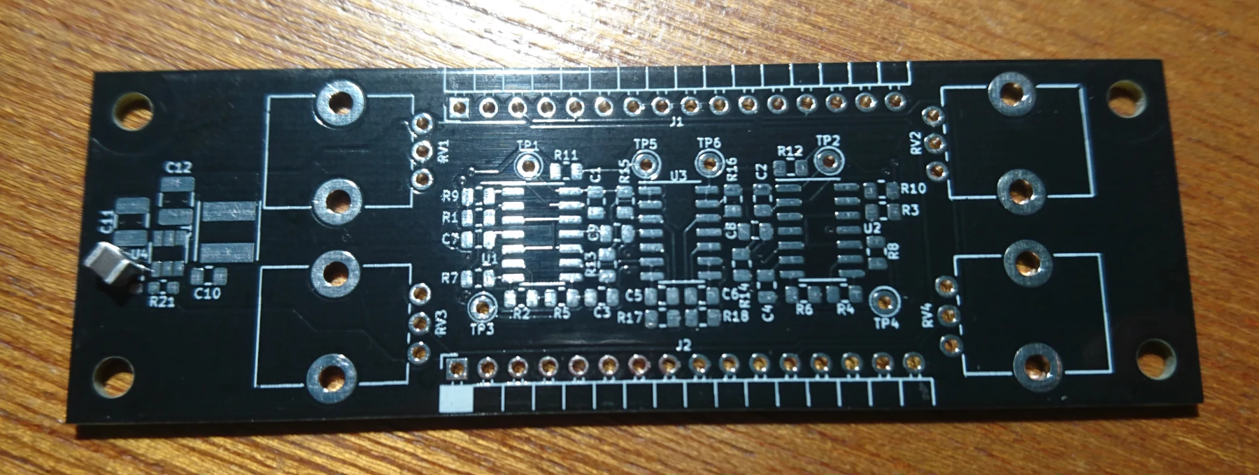 bare board
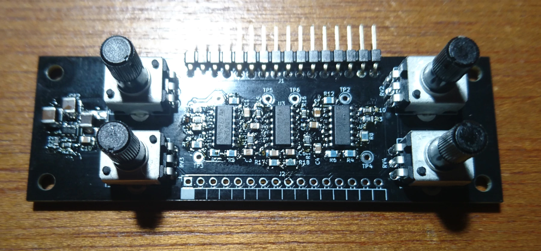 assembled board
One board has two separate chaotic circuits. Each circuit uses six opamps: five for the chaos part, plus one to buffer the V/2 reference voltage. Power is supplied through the edge connectors and stepped down to 4.5V to power the circuit using a switching regulator like on the LED boards. There are two pots per circuit: one to tune the circuit into the chaotic region and another to adjust the output amplitude.
testing
Now it's time to test the circuit. True to form, it's not very chaotic for most values of the adjustment pots (RV1, RV2) - in fact, one half of the board I assembled never seems to "cross over" from one side of the double scroll to the other. I will have to play with the resistor values some more.
All that aside though... it works!
It doesn't drive very hard - the waves pretty much dissipate before even reaching the other side of the array. Because each board has two drivers that are not necessarily in phase, they tend to "fight" each other. Driving more units with the same driver or adding more drivers would make the array more active. This is a matter of preference though, and this driver does essentially what I wanted it to.