4" spark gap coil
This is the first Tesla coil I built. It is a spark gap coil, with a secondary wound with about 1000 turns of 22AWG wire on 4" SCH40 PVC pipe, and a 10 turn 1/4" copper tube primary with a movable tap. Below are the descriptions of the other major parts, along with images and videos of it in operation. Click each picture for a larger version.
power supply
Because high power high voltage transformers were expensive and difficult to come by, I decided to scrap microwave ovens for their transformers. Microwave oven transformers (MOTs) typically output just over 2kV AC and can push up to 1A, an astounding amount of power for something relatively small. They pay a price for their compactness - their efficiency suffers as the core is not quite large enough and runs in saturation.
The 2kV output of a single MOT is not really enough to run a Tesla coil, because the spark gap separation must be very small. This combined with the high current makes the gap very difficult to quench. Consequently, Tesla coils that use MOTs must place several in series, typically four or six, to create an output of 10kV or more.
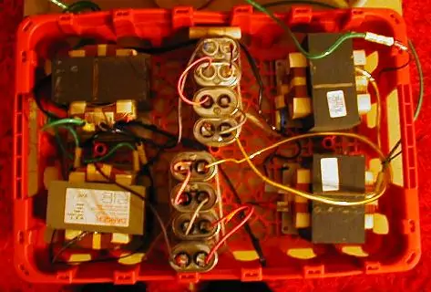 |
This is the original power supply for the coil. It consists of four microwave oven tranformers (MOTs) wired in two banks of two. The banks form the two halves of a center-tapped supply, and each bank is wired with the primaries and secondaries in series and in phase to take 240V from a dryer outlet and output roughly 5000 volts. Capacitors sit between the secondaries of each transformer in each bank to provide power factor correction and to limit output current. The output from the whole pack is therefore about 10kV. A 20oz drink crate provides a sturdy and portable base. |
 |
This is the current supply. Something, perhaps stray metal shavings, shorted out the secondaries of two of the MOTs on the original supply. They were replaced, connections were made more robust and better isolated, and PVC output bushings were added; you can see them on the right. |
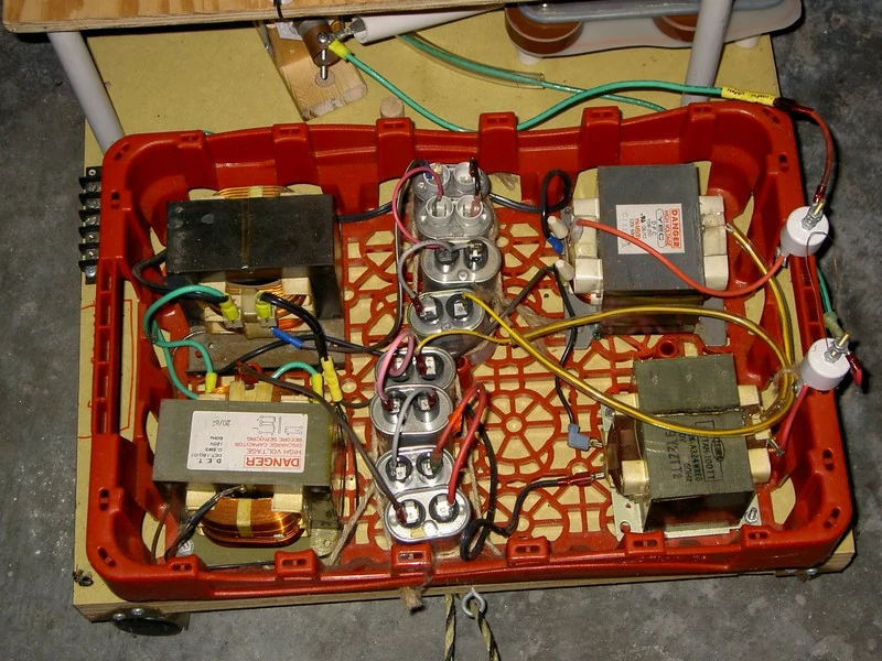
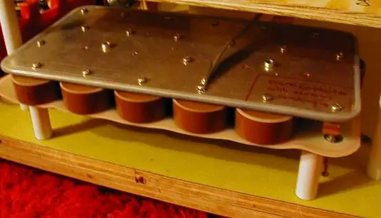
main capacitor
 |
This is the original capacitor bank, i.e. 'tank cap'. Its purpose is to store energy from the power supply and discharge a few hundred times per second into the primary coil. It consists of 19 TDK UHF-9A 2nF 40kV ceramic pulse caps. Ceramic caps are not usually a good choice for Tesla coils, but these were designed specifically for quick discharges in rapid succession. |
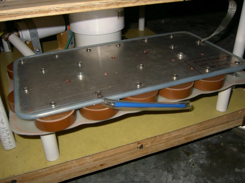 |
This is the current capacitor bank. The old one was dismantled and the plates were reused to make a bank of 17 4nF 20kV capacitors of the same type as the original. The extra capacitance nearly doubles the energy per discharge for longer sparks, and the loss in voltage rating is unimportant in this case. A 50Mohm high-voltage resistor was placed across the bank to dissipate charge after turning the coil off. This resistor is not necessary when the bank is in the circuit, as it will discharge through the power supply, but it prevents charge from accumulating if disconnected. |
spark gap
There were several iterations of spark gap for this coil. A Tesla coil spark gap must be adequately cooled and quenched, so for all but the smallest coils there is typically airflow over the gap or motion of the electrodes. I tried both variants; it turns out that a static gap with airflow produced the best performance on this coil.
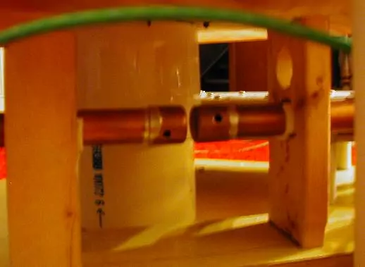 |
The original spark gap was simply two copper pipes with end caps soldered on, held in a wooden rig. During operation, a leafblower was positioned to blow air across the gap to cool the gap and quench the spark. It worked fine, but the leafblower was not attached to anything and would frequently slide out of position. |
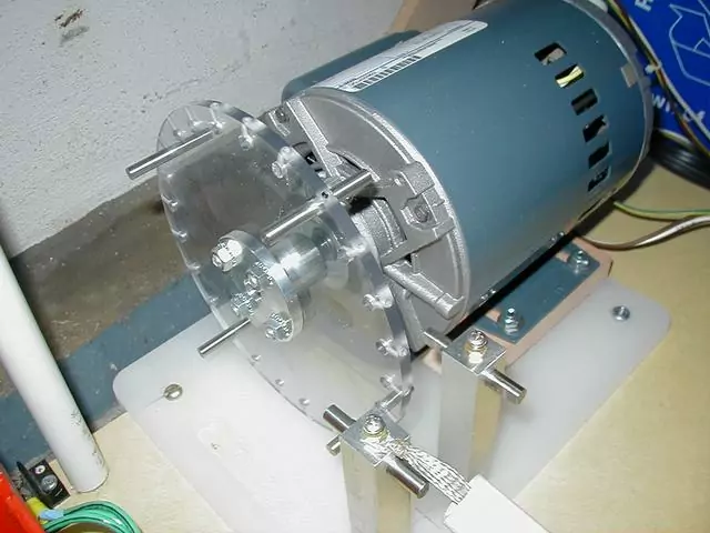 |
The next gap was a synchronous rotary spark gap (SRSG). A 3450RPM induction motor was modified by grinding two flats on the rotor, thus making it a 3600RPM motor that spins in phase with the AC line voltage. The polycarbonate rotor can hold various numbers of electrodes, which bridge enough of the gap between the stationary electrodes that a spark can form. This gap is quickly opened again by the rotation of the disk. During testing, it was found that this gap had a serious problem of unknown cause: it sucked ass. Spark length was about half that achieved from the previous gap. Maybe more tuning will be done later, by varying the positions of the electrodes, but for now it sits on a shelf. |
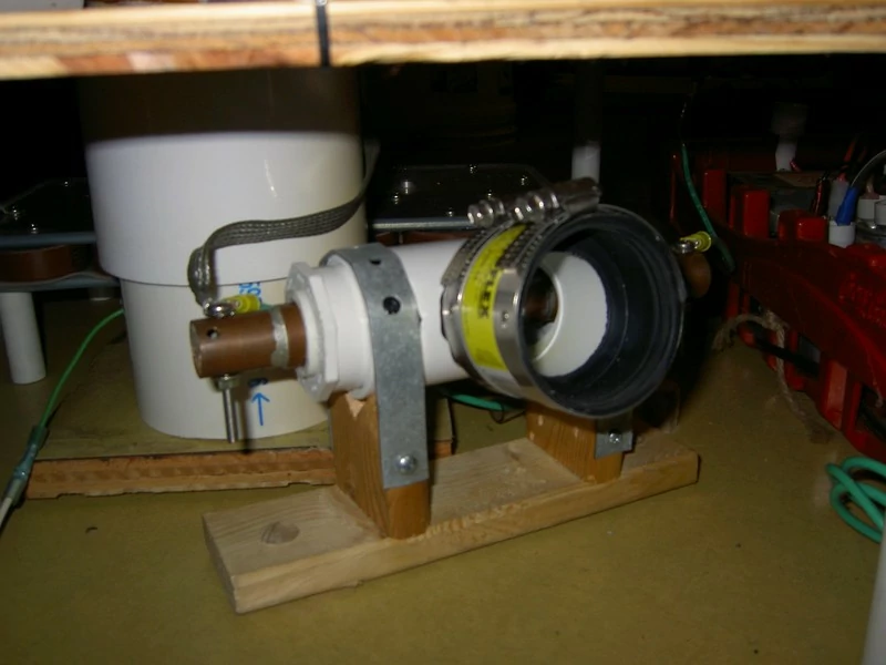 |
Here is the newest and best-performing spark gap. It is a "sucker gap" turned inside out, using a vacuum to suck air through the hollow electrodes through holes in the gap face. This produces fast outward airflow over the gap face, quickly blowing out the spark and cooling the electrodes. It is enclosed in a PVC tee fitting, which blocks most of the light from the arc, making the streamers from the top more visible. A wet-dry vac is attached to the rubber adapter during operation. |
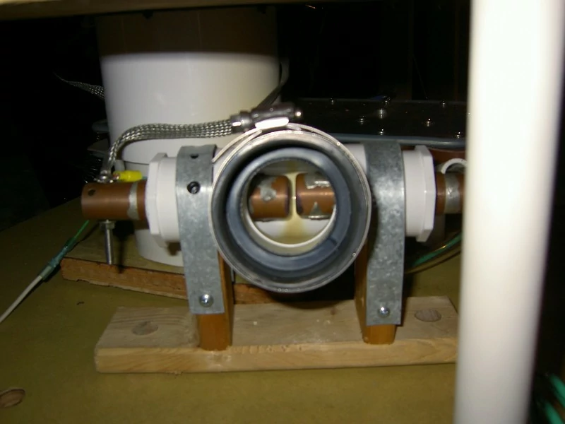 |
Another view of the sucker gap, showing the electrodes. Note that the heat and UV from the arc have discolored the PVC inside. Arcs really do generate a lot of UV - they're not good to look directly at! |
operation
At first light (the first couple of photos), the coil could produce streamers about three feet long.
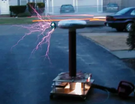 |
Streamers from first light. I hung a CD off a nail as a breakout point; it is getting rather fried here. |
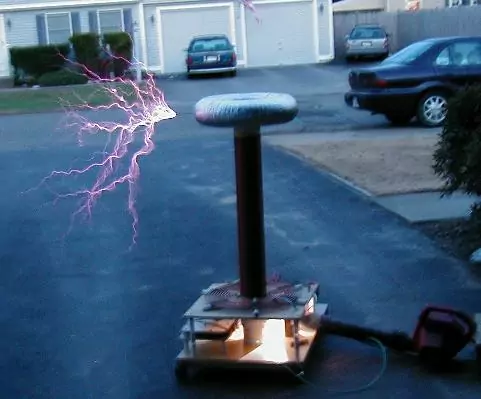 |
This time without the CD. Note the leafblower keeping the gap cool. This was not the greatest setup. |
After a series of upgrades, using the latest components described above, it could produce streamers of some 4-5 feet. Here's a video of the coil. The noise at the beginning is the wet-dry vac for the spark gap.